The following guide provides information on how to get a NetScaler cluster up and running.
NetScaler clustering can provide active-active traffic processing on 2 or up to 32 NetScaler appliances either physical or virtual. Each appliance must be of the same license type, software build, hardware build (MPX/SDX) or virtual build (VPX/SDX).
Clustering is part of NetScaler Enterprise or Platinum licenses.
The following NetScaler features are not supported in a cluster:
- SSL Certificate Bundles
- DNSSEC
- TFTP (Note: Is supported on NetScaler 12.0+)
The following NetScaler 11.1 features are supported at a node level, meaning that they can run on a single node in a cluster.
- Integrated Caching https://jgspiers.com/netscaler-integrated-caching/
- Surge protection
- AppFlow
- Full VPN or Clientless VPN
For a full list of features not supported at all or supported at a node level, see https://docs.citrix.com/en-us/netscaler/11-1/clustering/cluster-features-supported.html
♣ Create Cluster
♣ Synchronize Cluster Files
♣ Precision Time Protocol
♣ Statistics
♣ Cluster SNIPs
♣ Node Groups
♣ Traffic Flow
♣ Steering
♣ Cluster Quorum
♣ Admin, Operational and Health states
♣ Equal Cost Multiple Path (ECMP)
♣ Cluster Link Aggregation
♣ Retain connections on cluster
♣ Command Propogation Failures
♣ Node level configurations that are supported
♣ Migrate NetScaler High Availability pair to a NetScaler Cluster
♣ Backup and Restore
♣ Troubleshooting
Create Cluster
To create a cluster, on node number one, navigate to System -> Cluster -> Manage cluster.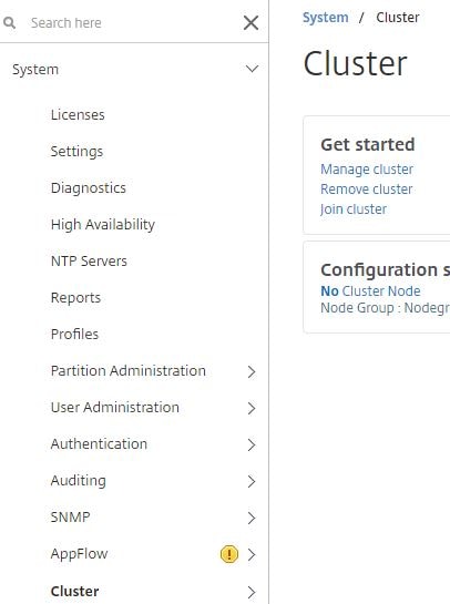
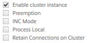
Enter a Cluster instance id and IP for the cluster (CLIP). If the cluster nodes reside on different networks, check INC Mode. If you do not want packets to undergo any steering, check Process Local. Click Continue.
Note: When using INC Mode, you’ll likely have SNIPs for each NetScaler cluster node, also known as spotted SNIPs. Having a single SNIP across all nodes (striped SNIP) is not supported when INC Mode is enabled. Cluster nodes from the same network must be added in to nodegroups that include other nodes from the same network. As en example, a London and Glasgow datacentre, the cluster spans across both regions using INC Mode. Two nodegroups are created, one containing the Glasgow appliances, and the second storing the London nodes. Nodegroups are explained later. 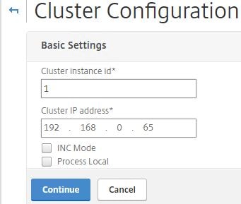
Give this node a unique Node ID. In my case I’ll have three nodes labelled 1, 2 and 3. Specify the Backplane interface which is the interface used to communicate with other nodes. This should not be the management interface. Additional interfaces should be added to each node to serve client and server traffic. Set the State to Active, this can also be Passive or Spare. Set the priority on all nodes to the same value for the cluster to choose a random node to be the Configuration Coordinator. If priorities are different between nodes, the node with the lowest priority will be elected as the Configuration Coordinator for all the times it is online and healthy. If this node goes down, the lowest priority node is elected and so on. Click Done.
Note: A Configuration Coordinator owns the Cluster IP address, and replicates configuration out to the other node members using the NSIP address. It acts as a master node. The first node you use to create a cluster is the Configuration Coordinator until either it goes down or a node with lower priority is added to the cluster.
Note: The state of MAC spoofing on Hyper-V, VMware or XenServer hypervisors can affect the steering mechanism on the cluster backplane. Make sure MAC spoofing for XenServer is disabled, enabled for Hyper-V and enabled for VMware along with enabling Forged Transmits.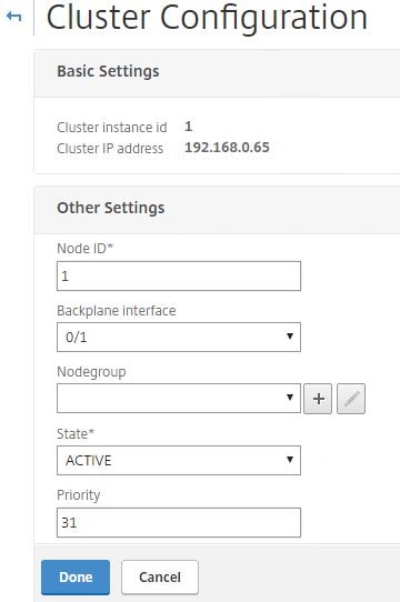
Click Yes. The cluster will be ready to accept new nodes at this stage. 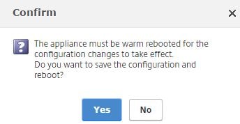
Log back in to the node, navigate to System -> Cluster -> Nodes -> Add. This process adds a second node remotely. 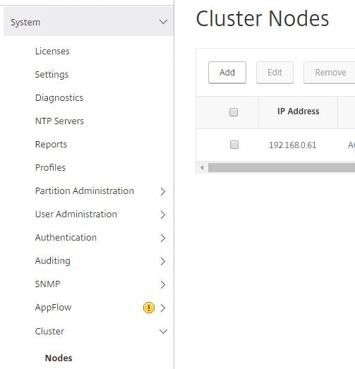
Enter a unique Node id, enter the NSIP address of the second node and specify the Backplane interface. The first value of “2” in the Backplane Interface field constitutes the Node id number. The 0/1 value is simply the interface ID. This allows the cluster to uniquely identity each node. Specify the same priority as node 1 or a different priority if you prefer. Check Execute join command and reboot the remote system.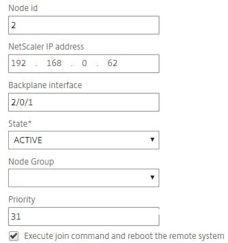
Enter nsroot credentials of the remote node and the current configuration coordinator. Click Create. 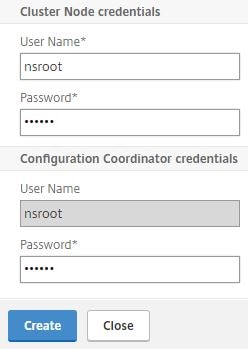
Click Yes. 
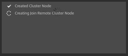
The second node will show as UNKNOWN whilst is is being restarted.
Note: When a node is added to the cluster, clear ns config -extended is ran on the node to clear the nodes configuration apart from VLAN and NSVLAN. If the cluster is an L3 cluster (nodes in separate networks using INC) then network configuration is not cleared.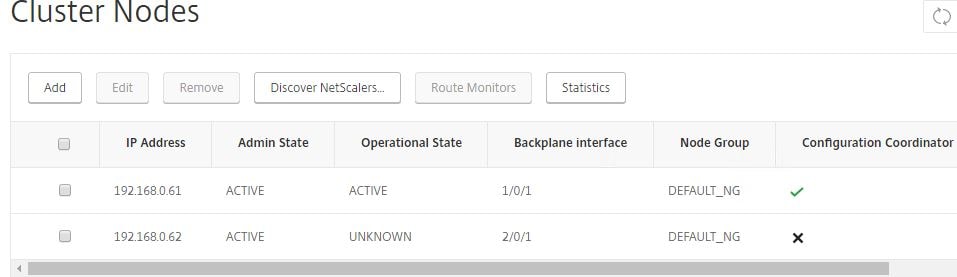
Once the node comes online it should return an operational state of ACTIVE and be joined to the cluster. 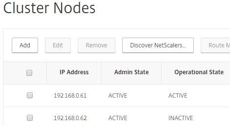
Another way to add a node, which I’ll do for the final third node is to log on to one of the existing cluster nodes and navigate to System -> Cluster -> Manage cluster -> Add. Enter details of the node as below and click Create, this time leaving Execute join command and reboot the remote system unchecked. 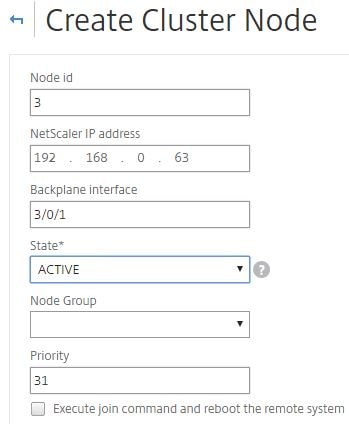
The node will appear as unknown for now.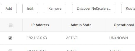
Log on to the third node and navigate to System -> Cluster -> Join cluster. 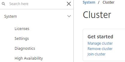
Enter the CLIP and password to the nsroot account of the configuation coordinator. Click OK. 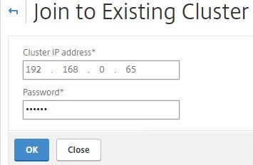
Click Yes. 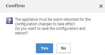
At this stage, you have a three node all active cluster, sharing the same configuration. You can also discover netscalers that are on the same subnet as the current node, simply by clicking the Discover NetScalers button and scanning a range of IP addresses. Discovered NetScaler appliances can then be selectively added to the cluster.
If you need to remove a node from the cluster, check a node and select Remove. Doing this executes a clear ns config -extended command on the node being removed to clear the cluster configuration. The default VLAN and NSVLAN are not cleared from the node. When the node being removed is the Cluster Coordinator, that role along with the CLIP is assigned to another node, one that has the highest priority (lowest number). Removing all cluster nodes would eventually delete the cluster IP address when the last node is removed.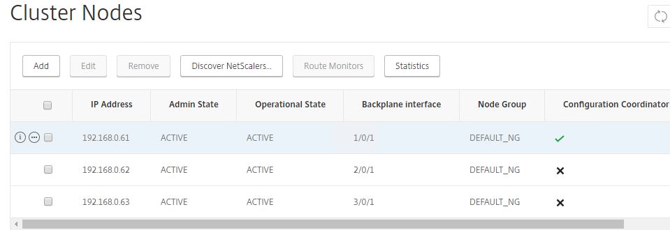
Synchronize Cluster Files
From one of the NetScaler cluster nodes, navigate to System -> Cluster -> Synchronize cluster files.
Using the drop-down box, you can choose to manually synchronize all files or certain ones such as SSL Certificate and Keys (when manually copied to NetScaler), or DNS records.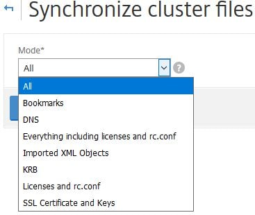
I menton SSL Certificate and Keys because when these are manually copied to the NetScaler Cluster Coordinator they aren’t automatically available on other cluster nodes.
All the files mentioned below are synchronized from the Configuration Coordinator once a node is added to the cluster or when you run a new command on the CLIP:
- /nsconfig/ssl/
- /var/netscaler/ssl/
- /var/vpn/bookmark/
- /nsconfig/dns/
- /nsconfig/htmlinjection/
- /netscaler/htmlinjection/ens/
- /nsconfig/monitors/
- /nsconfig/nstemplates/
- /nsconfig/ssh/
- /nsconfig/rc.netscaler
- /nsconfig/resolv.conf
- /nsconfig/inetd.conf
- /nsconfig/syslog.conf
- /nsconfig/snmpd.conf
- /nsconfig/ntp.conf
- /nsconfig/httpd.conf
- /nsconfig/sshd_config
- /nsconfig/hosts
- /nsconfig/enckey
- /var/nslw.bin/etc/krb5.conf
- /var/nslw.bin/etc/krb5.keytab
- /var/lib/likewise/db/
- /var/download/
- /var/wi/tomcat/webapps/
- /var/wi/tomcat/conf/Catalina/localhost/
- /var/wi/java_home/lib/security/cacerts
- /var/wi/java_home/jre/lib/security/cacerts
- /nsconfig/license/
- /nsconfig/rc.conf
Note: When configuration synchronization is processing upon adding a new node to the cluster, there may be intermittent traffic loss.
Click OK to perform a manual sync.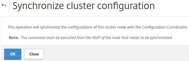
You can also synchronize files using the CLI command sync cluster files all or sync cluster files DNS for example.
Precision Time Protocol
Clicking Configure Precision Time Protocol(PTP) Settings allows you to change the PTP state. The default state is ENABLE. PTP is a protocol mainly used with Linux systems that is used to synchronize time between systems and in our case the cluster nodes. If you disable PTP as a result of time issues or for other reasons, make sure the cluster is configured for NTP with a reliable time source.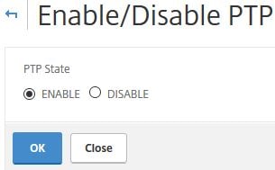 You can also disable PTP using CLI command set ptp -state disable
Statistics
Clicking Statistics shows cluster related statistics such as the total amount of steered packets, the cluster status, size and so on.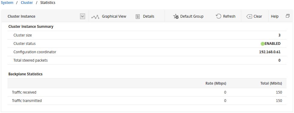
You can also view the statistics of a cluster node via GUI or using CLI command stat cluster node nodeid
Cluster SNIPs
Just like a single NetScaler, the cluster can be assigned a SNIP address which is shared between all nodes (striped) or assigned to one or more single nodes (spotted). When creating a SNIP, select ALL_Nodes under Owner Node.
Note: When USIP is disabled, Citrix recommend using spotted SNIP addresses. Also, when running in INC Mode, striped SNIPs are not supported.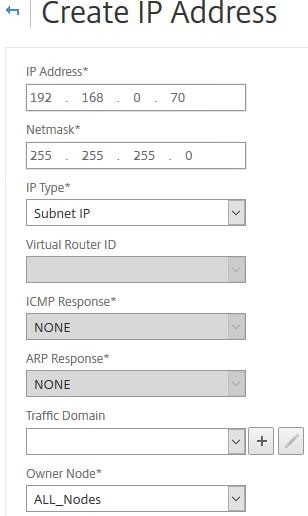
The SNIP will appear as below.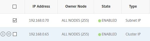
Node Groups
Node Groups are groups one or more nodes can optionally be a member of if you want certain configurations (entities) to be active only between certain node members or you want to configure redundancy for nodegroups. As you are now aware, the Cluster Coordinator replicates configuration out to all nodes (striped). Whilst you cannot stop that, you can stop configurations from being active on specific nodes. For example, you want only certain Load Balancing vServers or services to be active on some but not all of the nodes. If an entity is active on one node (in a Sticky nodegroup) it is referred to as a spotted entity. If an entity is active on more then one node, it is referred to as partially striped. To create a nodegroup, navigate to System -> Cluster -> Node Group -> Add.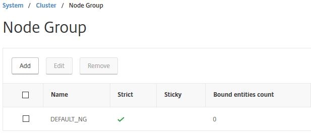
Specify a name. You can optinally set the state of the Node Group (Active/Spare/Passive) for redundancy and failover for example having an Active Node Group and a second Passive or Spare Node Group which is capable of taking over. Keep in mind that any node you make a member of this group will use the state of the Node Group. If a single node has an admin state of passive and is added to an active Node Group, the node will become active. The Strict checkbox if checked means no other cluster node is added to the Node Group if one of the existing Node Group members goes down. If unchecked and a Node Group member node goes down, a non-member is added to the Node Group and picks up the configuration. This node is called the replacement node. When the original node comes back online, the backup node is replaced. The Sticky checkbox when enabled results in only one node being allowed to be bound to the Node Group. This is the owner node. When Sticky is checked and the owner node goes down, a backup node takes place and continues to serve traffic even when the original owner node comes back online. When unchecked, the original owner node takes over when back online. Sticky and Strict cannot be used together, so one of the options will be greyed out depending on what you have chosen.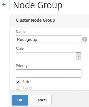
To bind nodes to the Node Group click No Cluster Node.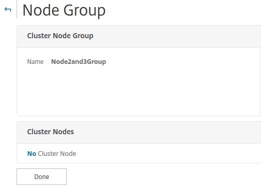
Select one or more nodes to bind.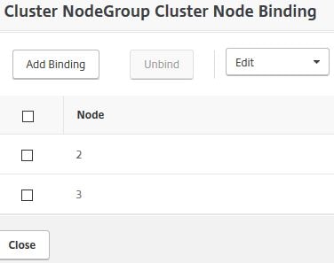
Now you can attach entities to the Node Group. These objects will be made active on the Node Group members. Select Load Balancing Virtual Servers.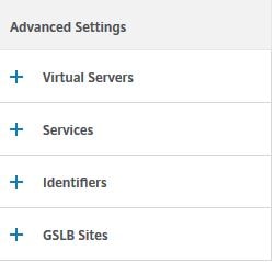
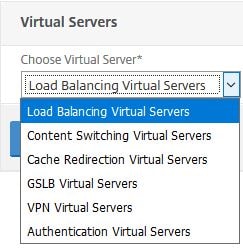
Select one or more servers, click Select.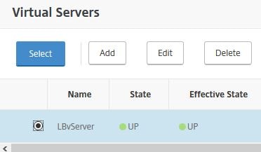
Click Done. 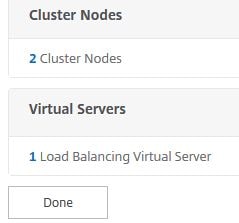
To create multiple nodegroups for redundancy, for example, you could create nodegroup1 with two active nodes, and a second nodegroup2 with 2 spare nodes. When one of the nodes in nodegroup1 goes down, the nodegroup is counted for nodes and compared with the number of nodes in other active nodegroups by priority. If another active nodegroup has a higher or equal node count, that nodegroup is made operationally active. If not, the spare nodegroup (nodegroup2) is checked.
Note: You cannot bind entities to a nodegroup when that entity has dependencies on another entity that isn’t bound to the nodegroup. Remove the dependency first, add both entities to the nodegroup then add the dependency back. For example, a vServer and spillover vServer or a Content Switching vServer with multiple LB vServers attached.
Note: GSLB is supported when GSLB sites are bound to nodegroups that contain a single cluster node. NetScaler Gateway is supported when VPN vServers are bound to nodegroups that contain a single cluster node with Sticky enabled on the nodegroup. AppFirewall is supported in striped or partially striped configurations. https://docs.citrix.com/en-us/netscaler/11/security/application-firewall/appendixes/cluster-configuration.html
Traffic Flow
Since all nodes act as a single entity using the CLIP, traffic that reaches the cluster must be routed to an appropriate node (flow receiver). Having a cluster with nodes that are active, spare or passive will obviously affect how traffic is routed. In the case of active nodes, ECMP (Equal Cost Multiple Path) or Cluster Link Aggregation is used to distribute traffic effectively. When NetScalers are operting in INC Mode, only ECMP can be used. When traffic reaches the flow receiver, the flow receiver then determines which node must process the traffic. Once a node is determined, the traffic is steered to the flow processor over the backplane if the receiver and processor nodes are on the same network or through a GRE unencrypted tunnel if receiver and processor nodes are on different networks.
Note: The fact that GRE tunnels are unencrypted means you are advised to secure the tunnel with IPSec encryption if traffic flows over the internet.
Steering
You can disable steering by checking the Process Local on the cluster instance. This means once the receiver receives traffic, it also acts as the processor. An exception to this is when the receiver does not own the required entity in a spotted or partially striped configuration. In this case, steering is still performed, however to the destination node which holds the service.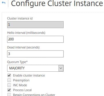
Note: When steering is disabled, striped SNIPs are not supported, L2 mode must be disabled, traffic flowing to the CLIP is steered to the Configuration Coordinator, MPTCP and FTP does not work.
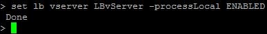
To disable steering on a particular Virtual Server, run command set lb vserver vServerName -processLocal ENABLED.
Cluster Quorum
To configure the cluster quorum, navigate to System -> Cluster -> Manage Cluster -> Quorum Type.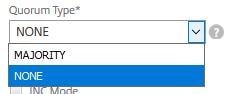
Majority – Recommended and requires the majority of nodes (in my case two) to be online for the cluster to stay UP.
None – No quorum is defined.
Admin, Operational and Health states
By navigating to Manage Cluster, you can see the Admin and Operational states of each node in the cluster. 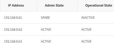
Admin states:
Active – Nodes are in sync with the cluster and serve traffic that reaches the cluster.
Passive – Nodes are in sync with the cluster but do not serve any traffic that reaches the cluster. This state can only manually be changed.
Spare – Nodes are in sync with the cluster and act as backup to active state nodes. When a spare node takes place of a down active node, the admin state remains spare but the operational state changes from inactive to active.
Note: If preemption is disabled (default), spare nodes continue to serve traffic even when the active node comes back online. If enabled, the spare node is preempted by an active node when the active node comes back online and finds the spare node serving traffic.![]()
Operational states:
Active – When the node is healthy and node is in active or spare admin state.
Inactive – When the node is in a passive admin state regardless of health, the node is in an active admin state and not health or when the node is in a spare admin state and not being used as backup.
Unknown – Node cannot receive heartbeats from other nodes
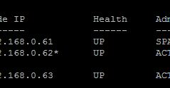
Health states are UP, NOT UP or UNKNOWN.
Health state criteria:
Up – When the following criteria is satisfied:
- Interfaces are up and enabled including backplane interface.
- Cluster synchronization operation is enabled and completed.
- SSL cards are available.
- Cluster Link Aggregation member(s) are up (if used).
Not up – One or more of the above criteria is not satisfied.
Unknown – The node cannot receive any heartbeats from other cluster nodes.
Equal Cost Multiple Path (ECMP)
As mentioned previously, traffic is distributed to cluster nodes effectively using either CLAG or ECMP. In the case of ECMP (requires NetScaler Standard edition), virtual server IP addresses are advertised by all active cluster nodes which means traffic can be received by any node, and steering directs t
he traffic to the correct node for processing. In the event you have spotted or striped virtual servers, these virtual IP addresses are advertised only on nodes where the virtual server is active. This helps to reduce redundant steering.
To configure ECMP, read the below useful resource links:
https://docs.citrix.com/en-us/netscaler/11/networking/ip-routing/configuring-dynamic-routes.html
https://docs.citrix.com/en-us/netscaler/11-1/clustering/cluster-overview/cluster-routing.html
Cluster Link Aggregation
As mentioned previously, traffic is distributed to cluster nodes effectively using either CLAG or ECMP. In the case of CLAG, interfaces from different cluster nodes are grouped together. CLAG is not supported on VPX running on XenServer, Hyper-V or AWS. There are also some other requirements to consider when running CLAG across VPX nodes.
To configure CLAG, read the below useful resource links:
https://docs.citrix.com/en-us/netscaler/11-1/clustering/cluster-traffic
-distribution/cluster-link-aggregation.html
https://docs.citrix.com/en-us/netscaler/11/networking/interfaces/configuring-link-aggregation.html
To remove a node from the cluster that uses CLAG, set the node as Passive and then remove the nodes interface from the Link Aggregation channel and cluster. To remove the node from cluster, use CLI command rm cluster node nodeid or use the GUI by navigating to Manage Cluster.
Retain connections on cluster
This option allows you to gracefully close down existing connections when you are removing a node from the cluster, adding a new node or when you are upgrading a node and need to t
ake it offline during this period. When for example you are upgrading a cluster, one node should be taken offline at a time. When gracefully shutting down or upgrading a node, navigate to System -> Cluster -> Manage Cluster and check Retain Connections on Cluster.
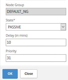
Now edit the node you want to upgrade, set the state to Passive and configure a delay in minutes which will determine how long the NetScaler maintains existing connections before purging them.
After the upgrade is done, return the node to an active state.
Note: When performing cluster upgrades or downgrades, configuration propogation is disabled until all nodes return to the same software version. This means you cannot make any configurational changes using the CLIP.
Command propogation failures
Using the CLI command show propstatus is a quick and easy way to display up to the last 20 recent command propogation failrues on all non Cluster Coordinator nodes. 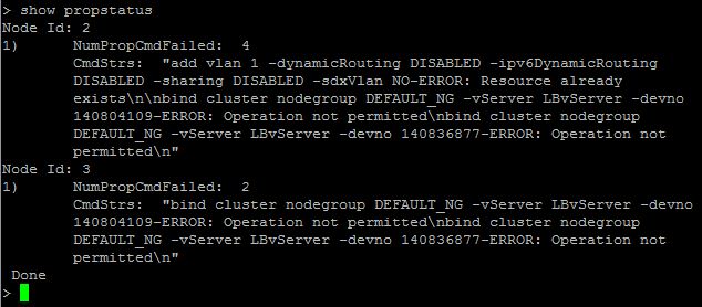
Node level configurations that are supported
NetScaler nodes in a cluster generally cannot be edited manually without configurations going through the NetScaler Cluster IP. There are some exceptions though, and the following list are configurations that can be done at a node level:
- reboot
- shutdown
- save ns config
- disable ntp sync
- sync cluster files
- force cluster sync
- add, remove, set, unset route
- add, remove, send -all arp
- set, enable, disable interface
- start, stop, show nstrace
- set, remove cluster node
- set, remove, enable, disable cluster interface
Migrate NetScaler High Availability pair to a NetScaler Cluster
See https://jgspiers.com/migrate-netscaler-ha-pair-cluster/
Backup and Restore
The backup and restore option normally found in the GUI is removed when nodes are operating in a cluster. You need to manually take backups of each node in the cluster.
Upon restoring, if Node1 was to fail, it is removed from the cluster and rebuilt/replaced. When Node1 is back online, it is added back to the cluster and you should restore the previously backed up ns.conf file and any other files as mentioned http://docs.citrix.com/en-us/netscaler/11-1/system/basic-operations/backup-restore-netscaler-appliance.html
If a cluster needs restored, you need to rebuld the cluster and repeat the above procedure on each node as they are added back the cluster.
There is a limitation if using CLA (Cluster Link Aggregation) and a MAC is generated from a faulty node causing the above procedure to not work.
Troubleshooting
show propstatus – Shows up to the last twenty commands that failed propogation on all non Cluster Coordinator nodes.
show cluster instance – Outputs the details of the cluster including the health state for each node, admin state and operational state. If there are any errors on a node such as no heartbeats being received, this will be flagged.
show cluster node id – Get specific information for a specific cluster node, including the sync state, health state, interfaces on which heartbeats are not seen etc.
- Note: You can disable heartbeats on specific node interfaces on NetScaler 12+. You cannot disable heartbeats on the backplane interface since it is required for maintaining connectivity between nodes.
show techsupport -scope cluster – Gather techsupport bundle to send to Citrix technical support/upload to CIS.
nstrace – Run nstrace on a single node or on the CLIP, which captures a trace on all nodes and stores them individually on each appliance /var/nstrace/. https://jgspiers.com/citrix-netscaler-traffic-capture-using-nstrace-nstcpdump/
Common Issues and troubleshooting tips – https://docs.citrix.com/en-us/netscaler/11-1/clustering/cluster-troubleshooting/ns-cluster-trouble-tip-ref.html
Heiko
January 23, 2018Hey,
is the cluster installation recommended in a vSphere environment? Because we are facing issues with this configuration. Do you know anything special for a VM environment? Thanks!
George Spiers
January 23, 2018There is no recommendation as such. If you need HA, use Load Balancing. If you need to scale out your web services across multiple NetScalers, use clustering.
Make sure the VPX builds are the same and they are running on a supported version of ESX.
If you need more performance from your NetScaler, increase the license and resources at a VM level or consider switching to MPX appliances.
Majeed
June 20, 2021We are using esxi 6.7 with netscaler vpx with a vmware distributed switch setup in a vpx HA setup. The distributed switch have 2 10 gig host Nics presented. The host are synergy blades that connect to synergy frame. The synergy switches connect in a mlag connection with 120gig presentation. We are reviewing vpx clustering trying to decide either if you can use CLAG or ECMP. Any pointers which way to go on blade architecture. If CLAG possible in such setup. Any advice much appreciated
Heiko
January 24, 2018Thanks for the reply 🙂 this helps me a lot!
joYk04
March 24, 2018Hi,
Thanks for the detailed and succinct guide on NS cluster.
We are currently running NS in HA pair and want to move towards clustering to optimise the use of the VPX and licenses. We have the VPX running on VMware.
I am somewhat not familiar with the cluster backplane. Does that resume to adopting one of the many VLANs configured in vSphere for the cluster backplane?
George Spiers
March 25, 2018Hi – it could be yes. For a cluster backplane you on each NetScaler dedicate a set of NICs (recommended to have these NICs in link aggregated channels) to a switch as per Citrix recommendation, but in the case of VPX you could have a vLAN dedicated to the cluster backplane, and bind NICs to that.
tianhao xie
December 26, 2020Hi,
if I set the channel backplane(0/LA/1: 0/1/1,0/1/2,0/1/3,0/1/4,) for MPX Cluster I think nsip will work on this port channel,does my dedicated management interface(0/0/1) need to be disconnected? Thanks for your answer
Kloe
April 1, 2021Hello George
Thanks for your article. I created a cluster instance and added a node to it. When I check, the Operational state of the node is “Inactive” and Health : “NOT UP”. I checked the interface state and found out that the backplane interface used for that node (1/1/1) is UP and the interface enabled and also HA Monitoring set to ON for that interface.
But not all the interfaces of this node are at UP state. Also, Cluster synchronization operation is enabled and completed for the cluster instance.
Please, which other parameter should I check to have this node switch to Health : “UP” and “ACTIVE” operational state?
vishnu
April 17, 2021Hi
when we are creating cluster does all the nodes in the cluster have to be on the same network?
If I have 3 VPX on SDX configuration and if the interfaces one of the VPX is 10/1 and other VPX is 100/1 will it cause any issues ?